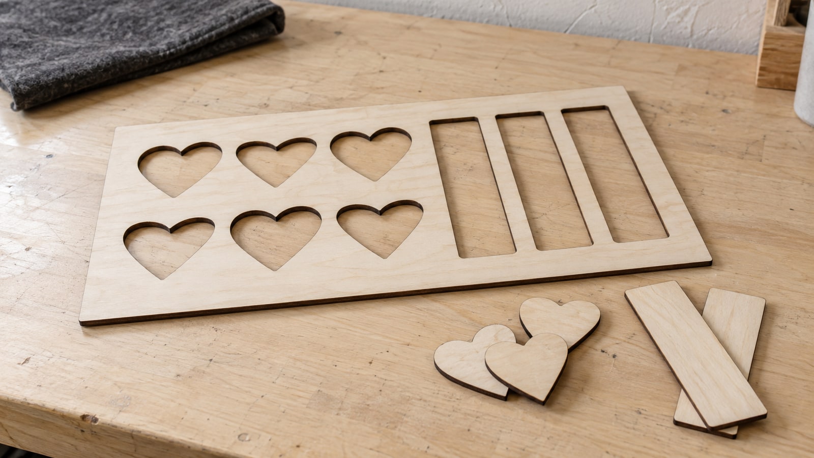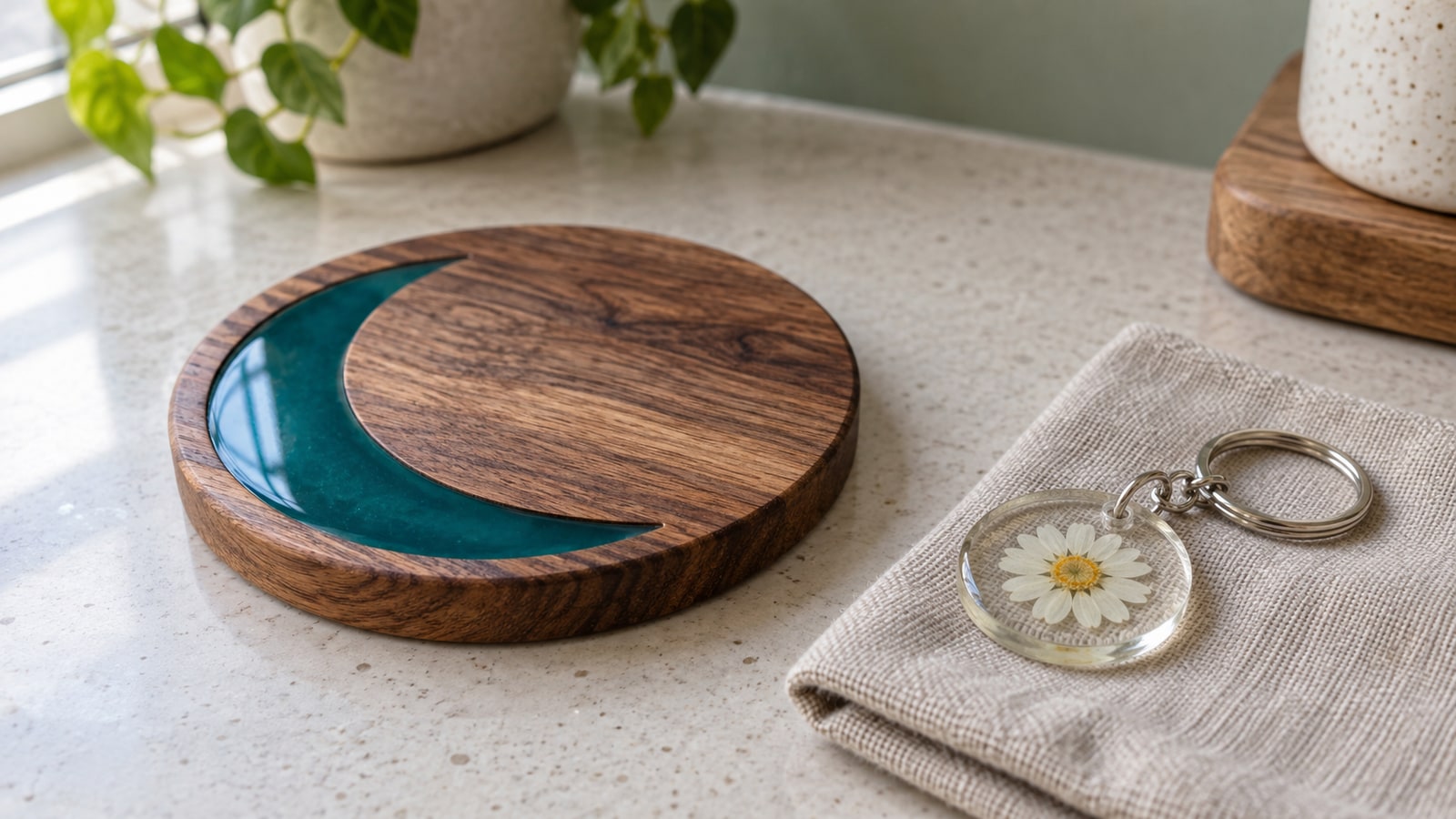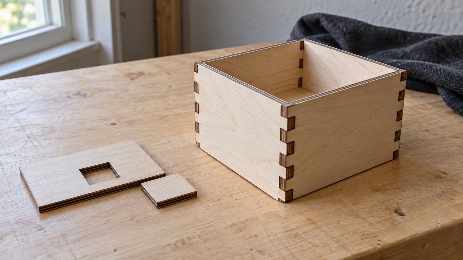
You cut the box, popped the pieces out, and the tabs rattle in their slots. Or the opposite: the inlay piece sits proud of its pocket and will not press home no matter how hard you lean on it. The design was drawn at exact size, the machine did what it was told, and the fit is still wrong.
This one has a clean explanation, and once you have it the problem stops being mysterious and becomes arithmetic you can do in your head.
Tip
The short answer: a cut removes width. A shape cut straight down its outline comes out about one kerf smaller than drawn, and a hole cut the same way comes out about one kerf larger, so a peg and a hole drawn to identical sizes end up with two kerfs of play between them. Fix it in one place, either the cut settings or the drawing, and never both.
Kerf is a width, not a setting
Kerf is the strip of material the cut takes away. A drag blade barely has one, which is why Cricut and Silhouette users almost never meet this problem. A laser has a real one, because the beam vaporises a lane of material along its path. A router’s nominal cut width is the bit diameter; runout, deflection and tool wear can change the measured result.
The line in your file has no width. It is a mathematical path. The cut that follows it does have width, and that width is centred on the path unless something tells the machine otherwise. Half of it comes out of the piece you are keeping, and half out of the part you are throwing away.
That is the whole mechanism. Everything below is a consequence of it.
The arithmetic that explains a loose joint
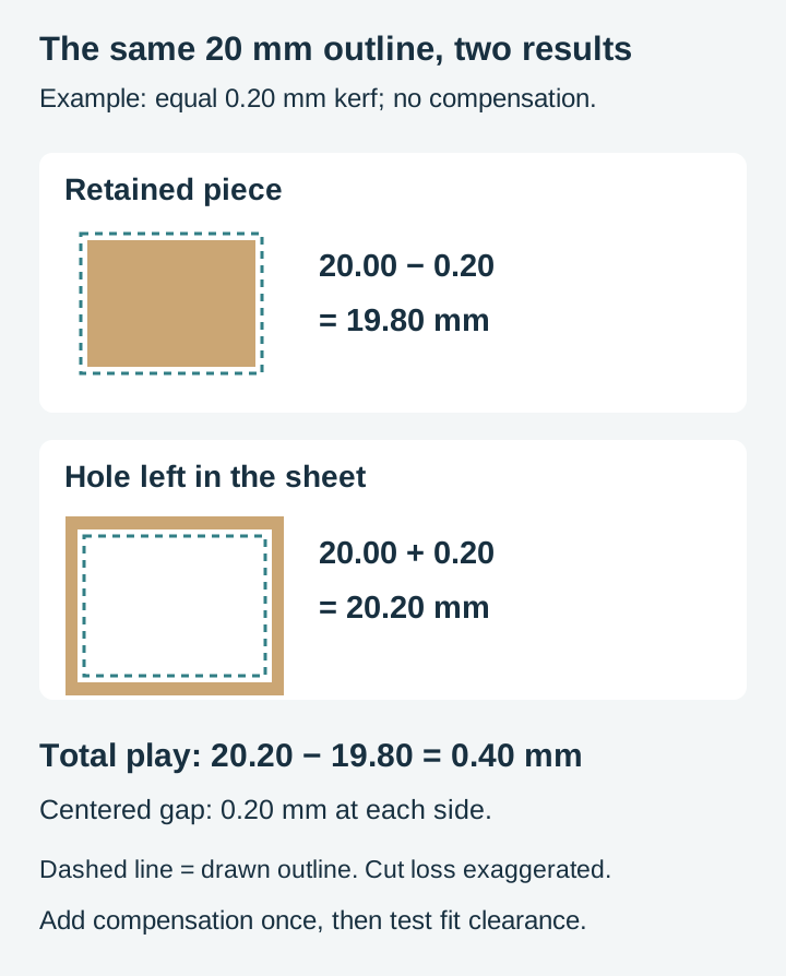
Call your kerf k. Suppose you draw a 20 mm square peg and a 20 mm square hole for it to sit in, and cut both with no compensation.
The peg loses half a kerf on each of its four sides, so it finishes at 20 minus k across.
The hole gains half a kerf on each side, because the waste falling out of the middle takes that material with it. It finishes at 20 plus k across.
Put them together and the gap is 2k, not k. With a kerf of 0.2 mm, that is 0.4 mm of total play, 0.2 mm of wobble on each side. This is why fits feel far looser than such a tiny number suggests, and why people assume something bigger must be wrong. The error stacks twice in every joint, once from the piece and once from the hole.
The tight version is the same equation run backwards. If your software is already compensating for the tool, when an inside or outside CNC toolpath is configured correctly, both parts come out at exactly the size you drew. Exactly is a problem. Vectric's own inlay documentation puts it plainly: parts machined to identical sizes "would not fit together without a lot of force which would damage the part". A joint needs designed clearance, and zero is not clearance.
So there are two failure modes with one root. Uncompensated cuts give you slop you did not ask for. Fully compensated cuts target zero clearance, which can still be too tight once machining variation, wood movement and glue are involved. The number you actually want sits between them and it is yours to choose.
Where the allowance belongs
There are three sensible homes for the correction, and picking the wrong one is what causes most of the remaining confusion.
In the cut settings. LightBurn has a Kerf Offset field in the Cut Settings Editor for layers in Line mode. Their documentation describes exactly the behaviour you want: positive values expand the border and negative values shrink it, shapes inside other shapes on the same layer have the offset direction inverted "to ensure that holes become the correct size", and the offset is applied only to the code sent to the machine rather than to the art. That last part is the reason to prefer this route. Your file stays true, and you keep one number per material instead of one file per material.
In the drawing. Offset the path in your vector editor before you cut. This is the answer when your software has no kerf field, which covers a fair number of cheaper diode machines and browser-based cutting apps, and it is also the answer when only one half of a joint should move. Offsetting in the drawing is permanent, so save it as a copy and label it with the material it was cut for. A file called box-3mm-ply-k02.svg will make sense to you in six months. A file called box-final-v3.svg will not.
Nowhere, deliberately. Plenty of work does not need it. A decorative ornament, a door hanger, a sign, a coaster: nothing mates with anything, and being a fifth of a millimetre under drawn size is invisible. Small retained features and exact outer dimensions can also need compensation, even without a mating joint.
The rule that matters more than any of this: apply the allowance once. Setting a global kerf offset and then also fattening the tab in the drawing is the single most common way to turn a loose joint into one that will not go together at all. If a fit gets dramatically worse after you "fixed" it, you almost certainly compensated twice.
When you do choose a side, put the allowance on the hidden half of the joint. If a compensated joint is too tight, widening its slot can preserve the visible tab outline. This adds clearance; it is the opposite of shrinking an oversized uncompensated hole. For an inlay, take the material off the plug and leave the pocket true, because the pocket edge is the line people see once the piece is glued in.
 Door Hanger Designs30 designs, commercial license included$3.99
Door hangers are a good example of a design that mostly ignores kerf right up until it does not. Cut a hanger on its own and the fit question never arises. Stack a second layer on top, or drop one inside a wreath ring, and suddenly you have a joint. The designs are drawn at true size with no allowance baked in, so if you want a piece to seat inside a recess you cut, the clearance is yours to add and yours to control.
Inside the line, outside the line, on the line
CNC software has asked you this question from the beginning, which is why router people meet kerf early and laser people often meet it late. Vectric's profile toolpath offers to machine outside, inside, or on the selected vectors, "automatically compensating for the tool diameter", with a separate Allowance value on top that overcuts or undercuts the shape.
Laser software mostly cuts on the line by default and expects you to supply an offset if you want something else. Same three choices, different vocabulary.
| Where the cut runs | Finished size against the drawing | Use it for |
|---|---|---|
| On the line | Outer shapes one kerf small, holes one kerf large | Standalone decorative pieces, anything that does not mate |
| Outside by half the kerf | Outer shape nominally true to drawn | Tabs, pegs, inlay plugs, parts that must measure right |
| Inside by half the kerf | Hole or slot nominally true to drawn | Slots, pockets, mortises, anything a part goes into |
Read down the middle column and the fit logic falls out of it. If both halves are cut true, they target zero clearance and may be difficult to assemble. So the working recipe for a press fit is to cut everything true, then add a small deliberate allowance to one half. Vectric suggests starting an inlay at 0.01 inches, which is about 0.25 mm, or 0.02 inches, about 0.5 mm, as the amount to open the fit up by. That is documented guidance for their software and a reasonable place to start a router inlay, not a universal constant.
Measure your own, and measure it last
There is no table of kerf widths worth trusting for your setup, because kerf follows the settings. Power, speed, focus, beam shape and stock can all change the result. Measure the actual cut instead of assuming one setting always changes it in the same direction.
Which gives you the sequencing rule that saves the most material: dial in your settings first, then measure kerf. Our walkthrough on running test cuts on a new material covers getting the power and speed right, including reading edge quality and taper. Do that, write the settings down, and only then measure. Measure first and you will have a number for settings you are about to abandon.
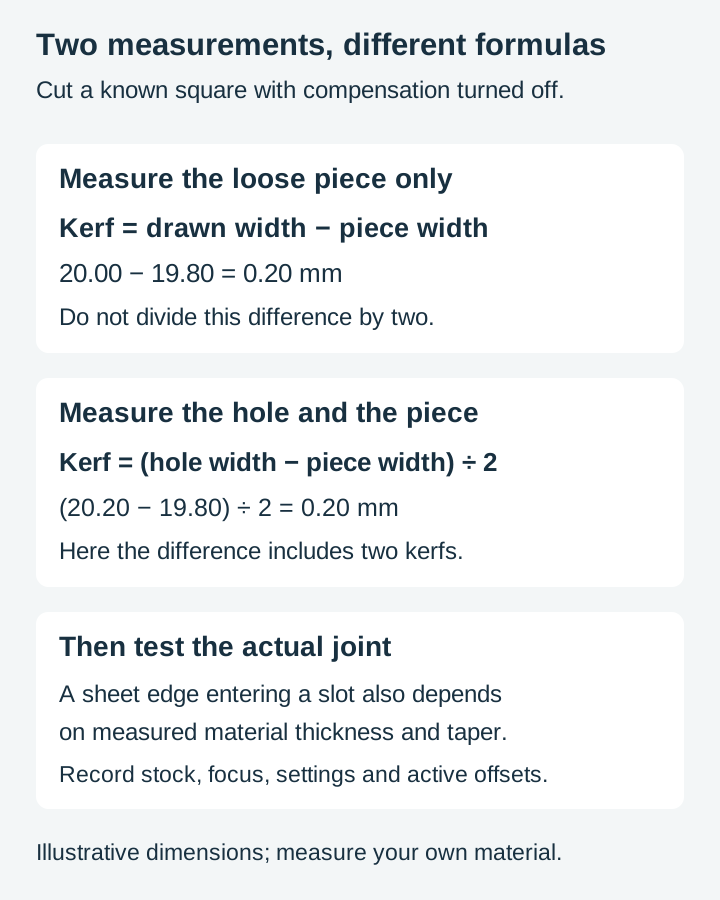
For the raw number, the square method is quick: cut a square of known size, measure the finished piece with calipers, and subtract the measured width from the drawn width. That difference is the full kerf, not half of it. For example, a 20.00 mm square measuring 19.80 mm indicates a 0.20 mm kerf and a nominal 0.10 mm offset per edge. If you instead measure both the hole and its loose insert, half their width difference estimates kerf. We walk through that in more detail in the post on how much detail survives on small items, where the same measurement decides whether fine gaps close up. LightBurn also ships a Vernier Kerf Offset test file that reads the value off a sliding scale, which is worth using if your calipers and your patience are not friends.
For fit specifically, there is a better test than a single number, because a joint is affected by more than kerf alone. Cut a fit ladder.
- Measure the actual sheet thickness in several places. Use a strip of that sheet as the mating part, inserted edge-on into each slot.
- Draw slots with widths spanning both sides of the expected fit. For uncompensated cuts, a useful center estimate is sheet thickness minus measured kerf; a compensated workflow uses a different starting point.
- Vary widths in small regular increments and record each drawn width plus any active software offset. The range must include a loose fit and a tight fit to be informative.
- Cut the sample from the intended stock with the final settings, without adding a second compensation.
- Try the sheet edge in each slot. Choose clearance for the material, handling and glue instructions. Brittle acrylic should not be forced into a press fit.
Write both numbers on the offcut and keep it. You now have a fit allowance for that material that already accounts for kerf, for thickness variation, and for how your particular machine cuts, without needing to separate those causes.
When the same file fits for someone else and not for you
This is the part that makes kerf feel personal. Someone posts a photo of the identical design assembled perfectly, and yours falls apart in your hands.
Nothing about the file is different. Kerf tracks beam width and focal spot, power and speed, material and thickness, and the state of your optics. A 40 W diode and a 60 W CO2 machine do not remove the same lane of wood. A router removes as much as its bit is wide. Even the same machine on the same sheet gives a different number after a lens clean.
There is a second cause that gets blamed on kerf constantly and is not kerf at all. If your slots are wrong by a quarter of a millimetre or more, look at the board before you look at the beam. Plywood and MDF are sold at nominal thicknesses that the actual sheet only approximates, and a finger joint slot is drawn to material thickness. Both kerf and sheet thickness can shift the fit by fractions of a millimetre. A 2.7 mm sheet differs from a 3 mm design assumption by 0.3 mm; neither cause can be ruled out from that number alone. Calipers on the sheet, every time, before you blame anything else.
Routers add a third cause that catches laser users moving over. A round bit cannot cut a square internal corner, so a square tab will not seat fully into a milled slot even when both are the correct width. The corners of the slot are left with the bit's radius in them. The design-side fix is a dogbone or T-bone relief, a small circle tucked into each internal corner so the tab has somewhere to sit. Our CNC router SVG guide covers preparing files for a router in more depth, including why the bit diameter shapes so much of what a design can be.
A quick diagnosis list
This is a design-side troubleshooting order drawn from how files are built rather than from measurements we took, and every number in it comes from something you measure on your own material.
| What you see | Most likely cause | What to do |
|---|---|---|
| Every joint loose by the same small amount | No kerf compensation anywhere | For a cut peg and hole, grow the peg path and shrink the hole path by half a kerf each; verify software sign and nesting behavior |
| Nothing goes together at all after you "fixed" it | Compensated twice, in settings and in the drawing | Remove one of them |
| Slots wrong by a quarter millimetre or more | Board thickness, kerf, scale or compensation | Measure the sheet and test the cut before changing slot width |
| Snug one way round, loose flipped | Taper in the cut | Flip the piece, and check focus if the gap is large |
| Fit changed after a settings tweak | Kerf follows power, speed, and focus | Re-measure at the new settings |
| Acrylic cracks when you press it home | Allowance too tight for a brittle material | Step up one rung on your fit ladder |
| Thin retained strips disappear | Neighboring cut channels consume the strip | For parallel cuts with equal kerf k, retained width is approximately drawn spacing minus k. Test strength too |
Ornaments are where most people meet this
Slot-together ornaments are the friendliest place to practise, because the parts are small, the material is cheap, and a joint that is slightly loose is fixed with a drop of glue rather than a rebuild.
Take two copies of the same snowflake. Cut a slot from the top edge of one down to its centre, and a matching slot from the bottom edge of the other up to its centre. Each slot is one material thickness wide plus your fit allowance. Slide them together at right angles and you have a standing three-dimensional ornament out of two flat cuts.
Everything in this post shows up in that one joint. The slot width comes from the board, not the nominal thickness. The allowance comes from your ladder. Cut both slots on the line with no compensation and the two halves will lean on each other rather than lock.
 Winter Snowflake Designs36 designs, commercial license included$3.99
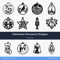 Christmas Ornament Designs38 designs, commercial license included$3.99
The snowflakes are worth a word on the drawing side too. Fine radiating arms with narrow gaps between them are exactly where kerf stops being a fit issue and becomes a survival issue, because each adjacent cut removes half its kerf from the retained strip. With equal kerf k, a strip of drawn width w retains about w minus k; strength may fail before the strip vanishes. The designs are drawn with that in mind, but at small finished sizes the maths is still yours to check: set the ornament to its real size and look at the narrowest gap before you commit a sheet.
The short version
Kerf is not a defect and it is not something to eliminate. It is a known width you account for once per material, in one place, using a number you measured yourself at the settings you actually cut with.
Get that number, write it on the offcut, and the fit stops being luck. Boxes close. Inlays press home. Ornaments lock instead of leaning.
Every design we sell is drawn at true size for exactly this reason, so the allowance stays yours to set. Packs are $3.99 with a commercial license included, and files ship as SVG, PNG, JPG, PDF, and EPS. If you want somewhere to practise the fit ladder, start with the holiday designs and cut something small enough that a mistake costs a scrap of ply.
Designs for this project
Frequently Asked Questions
Why are my laser cut pieces slightly too small?
Because the beam removes material as it travels, and half of that width comes off your piece. A shape cut straight down its drawn outline finishes about one kerf smaller across than you drew it, and a hole cut the same way finishes about one kerf larger. This is the expected geometry of an uncompensated cut. Check scale, motion and material as well if the error does not match your measured kerf.
Should I add kerf compensation to the SVG or in my cutting software?
In the software if it has a kerf field, because the value belongs to your machine, your material, and your current settings rather than to the artwork. LightBurn's Kerf Offset changes only the path sent to the machine and leaves the art untouched, so the same file works on a different material with a different number. Offset the drawing itself when your software has no kerf field, or when only one part of a joint needs the allowance.
Why does the same file fit perfectly for someone else and not for me?
Kerf is not a property of the file. It follows beam width, focus, power, speed, material, and thickness, so two makers cutting the same design get different finished sizes. A router changes it again, because there the cut is as wide as the bit. The file is drawn at true size on purpose so that each machine can apply its own allowance.
My tab fits at the top of the slot but not the bottom. What is that?
Taper. The cut is usually slightly wider where the beam enters than where it leaves, so a piece can feel snug one way round and loose the other. Flip the piece and try again before changing anything in the drawing, then check focus if the difference is large. Cut taper can also narrow near the focus and widen again, so do not assume it always runs in one direction.
Do PrintCutCarve files include kerf compensation?
No, and that is deliberate. Every path is drawn at true size, so what you measure in the software is what the design is. Baking in an allowance would be correct for exactly one machine on one material and wrong for everyone else.