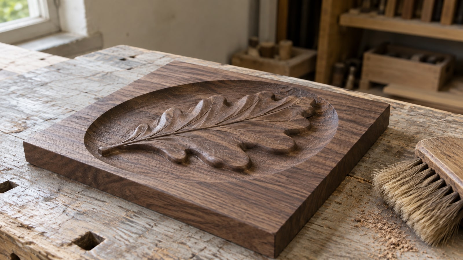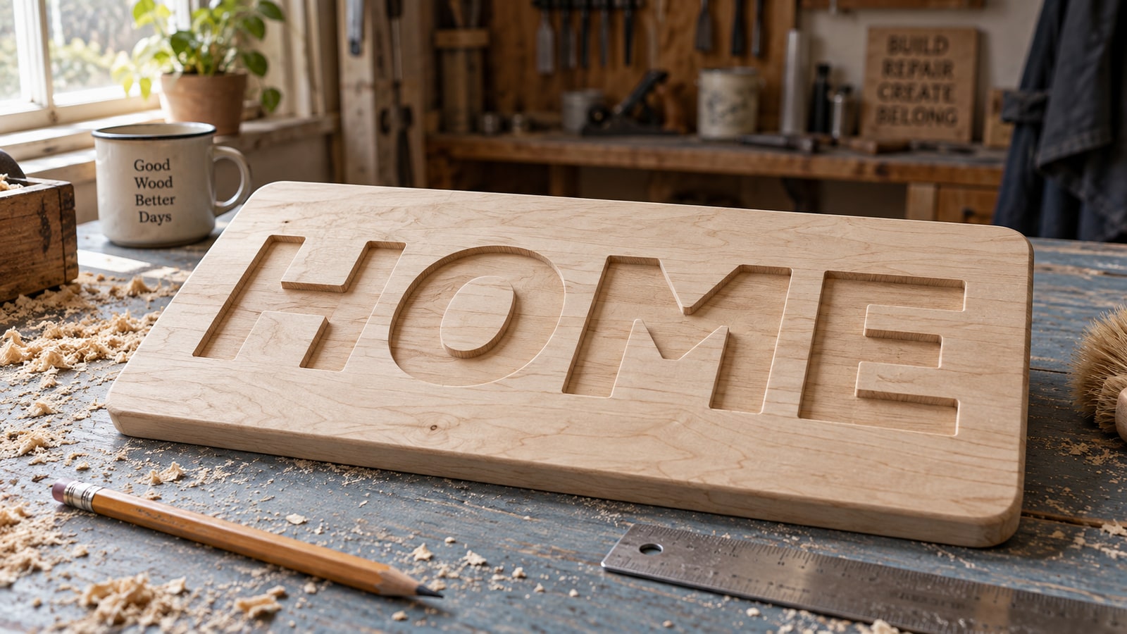
The design is on your screen and the router is on the bench, and the distance between them feels bigger than it should. Laser and vinyl people load an SVG and press go. CNC people get asked about toolpaths, stepdowns, tabs, and feed rates before a single chip flies, and plenty of good routers sit idle because that middle layer never quite clicked.
This guide is that middle layer. It walks the complete route from an SVG file to a carved board on a Shapeoko, X-Carve, Onefinity, or any other router: what CAM software does, which toolpath types produce which results, how to choose bits, and the file qualities that decide whether toolpath generation is a ten-second click or an afternoon of repair. That last part is our home ground, because we build cut files for a living.
Tip
Short answer: the chain is SVG file, then CAM software, then toolpaths, then G-code, then the router. The SVG defines the shapes, the CAM software adds depth and machining strategy, and the G-code tells the machine where to move. Clean, closed vector paths are what make the middle step painless.
What actually happens between the file and the cut
An SVG is pure 2D geometry: outlines, curves, shapes on a flat plane. It says nothing about depth, bits, or speed, because it was never a machining format. A CNC router, meanwhile, only understands G-code, a stream of instructions like "move to this coordinate at this height."
CAM software (computer-aided manufacturing) is the translator. You import the SVG, tell the software which shapes get which treatment, how deep, and with which bit, and it computes the toolpaths: the exact routes the spinning bit will travel. Export those as G-code, feed them to your machine's controller, and the router does the rest.
The practical consequence is worth internalizing early: depth lives in the CAM software, not the file. The same leaping-fish SVG can be a through-cut ornament, a quarter-inch recessed pocket, or a v-carved line drawing, depending entirely on choices you make at the toolpath stage. One good file is many projects. For true sculptural 3D, where the design itself carries height data, you want a different input format entirely; our depth map guide covers that world.
 Home Sweet Home Signs30 designs, commercial license included$3.99
CAM software that imports SVG
Every mainstream hobby CAM package imports SVG natively. The honest differences:
Carbide Create. Includes SVG import and common 2D toolpaths. Check the tier for your machine: standard G-code export for other machines requires Pro, which also adds 3D and advanced operations.
Easel by Inventables (free tier, Pro subscription). Browser-based, nothing to install, and it drives the machine directly as well as generating toolpaths. Great for first projects; you may outgrow its toolpath options later.
VCarve Desktop / Pro (paid). Vectric's package is the hobby and small-shop standard, especially strong at v-carving, nesting, and multi-bit jobs. If signs are your plan, this is the tool most sign makers land on. Our v-carving tutorial goes deep on that workflow.
Fusion 360 (free for personal use). Autodesk's full CAD/CAM platform. SVGs come in through the sketch environment, and the CAM side is enormously capable and correspondingly steeper to learn. The right choice when your projects head toward mechanical parts and joinery rather than decorative carving.
Before choosing software, check its import tools, export restrictions, and post-processor support for your controller. A trial or free tier can help you evaluate the workflow, but it may not include the output your router needs.
Importing the SVG: the five-step setup
The ritual is nearly identical across all of these programs:
- Start a new project and define the stock: the width, height, and thickness of the actual board on your machine.
- Import the SVG (File > Import, or a dedicated vector import button).
- Scale and position the design on the virtual stock. Vector art rescales losslessly, so size it to the project, not the other way around.
- Set your origin, the X/Y zero the machine will measure everything from. A corner of the stock or its center; just make the software and the physical setup agree.
- Create toolpaths for each part of the design, which is the real work and the subject of the next section.
The four toolpath types, and what each produces
Nearly every 2D CNC project is built from four strategies.
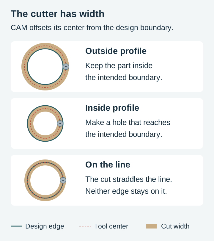
Profile (contour) cuts run the bit along the shape's outline, often through the material using multiple depth passes, to cut the piece out. You choose whether the bit travels outside the line (the piece keeps its true size), inside the line (holes keep their true size), or on the line. Cutouts, ornaments, signs shaped like the design itself.
Pocket cuts clear all the material inside a closed shape down to a set depth, leaving a recessed area with a flat floor. Recessed lettering, inlay cavities, backgrounds lowered so a design stands proud. Depth is yours to choose: an eighth of an inch reads as subtle, a half inch as dramatic.
V-carving traces paths with a v-shaped bit that cuts deeper where the design is wider, producing the tapered, hand-carved look that dominates professional sign work. It rewards specific design qualities, which is why it has its own tutorial.
Engraving runs a fine bit shallowly along the lines of the design, marking the surface without significant depth. It is the CNC equivalent of drawing, and it is how line-art detail gets added to an otherwise flat project.
Most satisfying projects combine two: pocket the background and profile-cut the board to shape, or v-carve the art and engrave a border.
A fifth one worth knowing about. Everything above is 2D work driven by paths. 3D relief carving is the step past it, where the machine follows a greyscale depth map instead of an outline and the bit rises and falls across the surface to build a sculpted form. It is how a carved medallion gets rounded muscle and feathering rather than flat stepped levels. The file is a different animal from an SVG, which is why it has its own explainer. If you want to try one, Craftgineer's ReliefMaker turns an illustration into a carving-ready greyscale map in the browser, which is far faster than painting depth by hand.
 North American Wilderness Relief Medallions30 designs, commercial license included$3.99
Choosing bits
Bit geometry is public knowledge and mercifully stable. The five that cover almost everything:
| Bit type | Best for | Common sizes |
|---|---|---|
| Flat end mill | Profile cuts, pocket floors | 1/8", 1/4" |
| Ball nose | 3D relief carving, rounded grooves | 1/8", 1/4" |
| V-bit | V-carving, lettering, fine detail | 60°, 90° |
| Downcut spiral | Clean top surface on plywood | 1/8", 1/4" |
| Upcut spiral | Fast chip clearing, deep pockets | 1/8", 1/4" |
Two geometric facts drive every bit decision. First, a flat end mill cannot enter a gap narrower than its diameter: a quarter-inch tool cannot clear an eighth-inch slot. Inspect the simulation for unreachable regions. A V-bit has a depth-dependent cutting width, so its nominal diameter is not the minimum detail width. Second, internal corners keep the bit's radius: a square inside corner from a round bit is physically impossible, which is why v-bits, with their near-point tips, own the fine-detail work.
For feeds and speeds, resist the urge to copy numbers from forum posts. Bit manufacturers publish chip-load charts for their tooling by material, and those charts plus your machine vendor's documentation are the legitimate starting points. Run conservative, listen to the cut, and adjust from there.
Why the file quality decides everything
Here is the section we can write with real authority, because these are the properties we build into every design we sell, and they are exactly the properties CAM software cares about.
Closed paths are non-negotiable. Pocketing and v-carving require the software to know what is inside a shape and what is outside, and only a closed path defines that. A path with a microscopic gap between its endpoints looks identical on screen and fails or misbehaves at toolpath time. Every CAM package has an open-vector finder for this exact reason.
Duplicate and overlapping paths poison toolpaths. Auto-traced files routinely stack two near-identical paths on top of each other. The software either cuts the line twice or gets the inside/outside logic wrong, producing pockets that invert or profiles that double-cut. Clean files carry one path per edge, no more.
Node hygiene shows up in the finish. A curve defined by a handful of well-placed nodes machines as one smooth, continuous motion. The same curve defined by five hundred jittery trace nodes becomes five hundred tiny line segments, and the machine physically stutters through them, leaving faceted edges and burning time. We rebuild traced art into low-node curves before it ships, and the difference is visible on the workpiece.
Detail has to respect the tool. Elements thinner than your smallest bit vanish; gaps narrower than the bit stay uncut. A design drawn for print can be full of hairline features that no router can reproduce. Designs drawn for cutting keep their features at machinable widths, which is a design decision, not a software setting.
If you are starting from a photo or a downloaded image rather than a proper vector file, vectorize before you import; our guide to converting photos to SVG covers the tools and the cleanup that follows.
Material notes for routed projects
- Softwoods (pine, cedar): forgiving and cheap, ideal first materials. Expect some grain fuzz that needs sanding.
- Hardwoods (maple, walnut, oak, cherry): the best-looking results and the crispest edges, with sharp bits and patience.
- Baltic birch plywood: stable, affordable, consistent. Use a downcut bit so the top veneer stays clean.
- MDF: carves fine detail beautifully and paints well; makes enormous quantities of fine dust, so run collection.
- Acrylic and plastics: doable with single-flute bits and the right approach; the material behaves differently enough to deserve its own reading.
For a fuller comparison of species and sheet goods, see the best wood guide.
Shop habits that save projects
- Fix the stock like you mean it. Clamps, quality double-sided tape, or screws through waste areas. Stock that shifts mid-job ruins the piece and can snap the bit.
- Plan support for the final cut. Tabs leave bridges of uncut material to retain a cutout; other workholding strategies may be appropriate. Keep the part secure through the last pass and remove any tabs after machining.
- Zero carefully. Most ruined first projects trace back to a Z-zero set wrong. Probe or paper-shim the bit to the stock surface and double-check which surface the CAM file expects, top or bottom.
- Simulate every job. Every CAM program renders a preview of the finished cut. Watch it to the end. It is free, and it catches wrong depths, missed regions, and inside/outside mistakes before they reach wood.
- Collect the dust. A dust shoe on a shop vac is close to essential for MDF and long jobs, for your lungs as much as the shop floor.
From file to first chip
The distance between screen and bench turns out to be four steps and one good file. Every PrintCutCarve pack is $3.99, ships as SVG, PNG, JPG, PDF, and EPS, and carries the closed, deduplicated, low-node paths this whole article has been arguing for, plus a commercial license for selling what you carve. These packs take particularly well to routed signs and plaques:
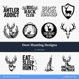 Deer Hunting Designs47 designs, commercial license included$3.99
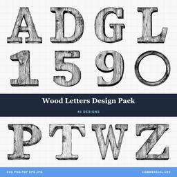 Wood Letters Design Pack40 designs, commercial license included$3.99
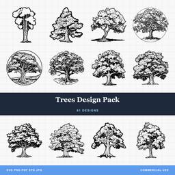 Trees Design Pack81 designs, commercial license included$3.99
When flat work starts feeling easy, two doors open next: v-carving for the carved-lettering look, and depth maps for true 3D relief.
Designs for this project
Home Sweet Home Signs30 designs, commercial license included$3.99Deer Hunting Designs47 designs, commercial license included$3.99Wood Letters Design Pack40 designs, commercial license included$3.99Trees Design Pack81 designs, commercial license included$3.99North American Wilderness Relief Medallions30 designs, commercial license included$3.99Frequently Asked Questions
Can a CNC router use SVG files directly?
Not directly. A CNC router runs G-code, which is a list of movement instructions. The SVG supplies the shapes; CAM software such as Carbide Create, Easel, VCarve, or Fusion 360 imports the SVG, lets you assign toolpaths and depths, and exports the G-code your machine actually executes.
Why does my CAM software refuse to pocket or v-carve my SVG?
Almost always because the vectors are open. Pocketing and v-carving only work on closed paths, since the software needs an unambiguous inside and outside. Run your CAM program's open-vector check or join the path ends in Inkscape, and watch for duplicate stacked paths, which confuse toolpath calculation the same way.
How detailed can an SVG design be for CNC carving?
No feature can come out narrower than the bit that carves it. A quarter-inch end mill cannot produce an eighth-inch slot, and internal corners always keep the bit's radius. For fine detail, use a smaller bit or a v-bit, whose tip reaches into details a flat end mill cannot, and expect longer run times as bits get smaller.