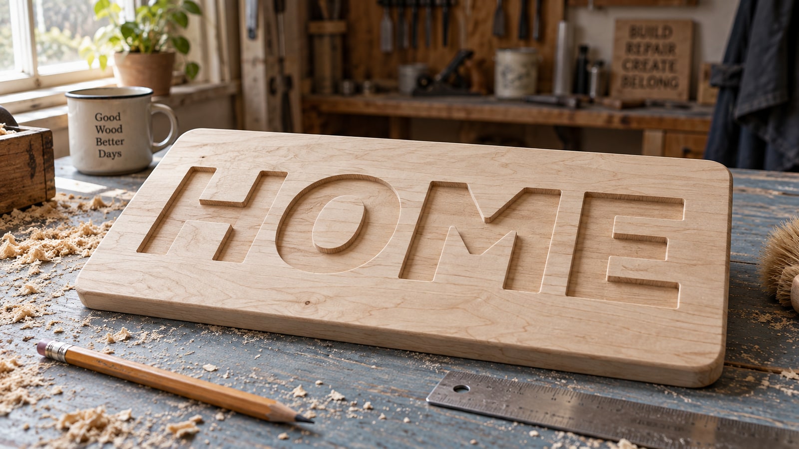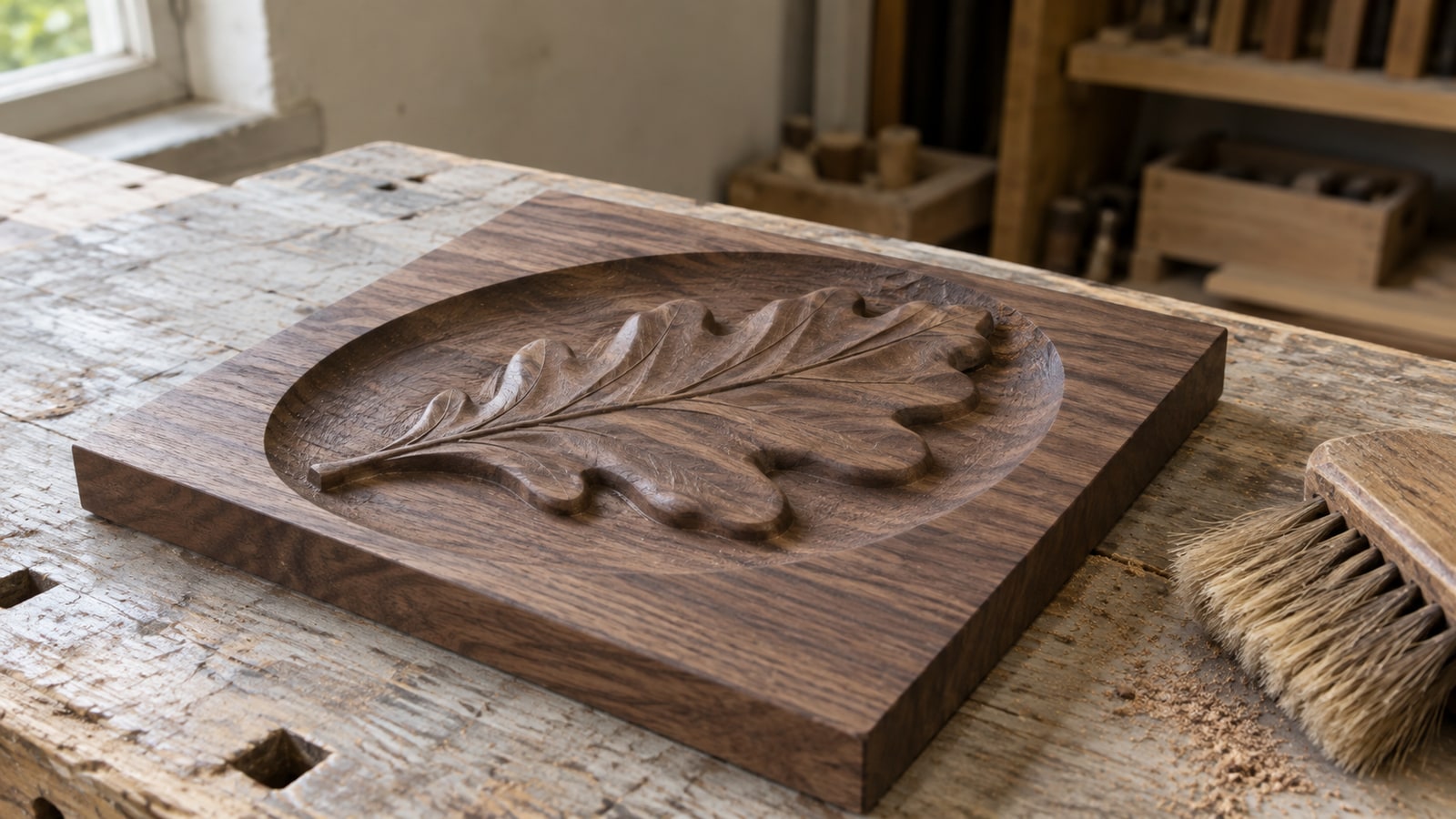
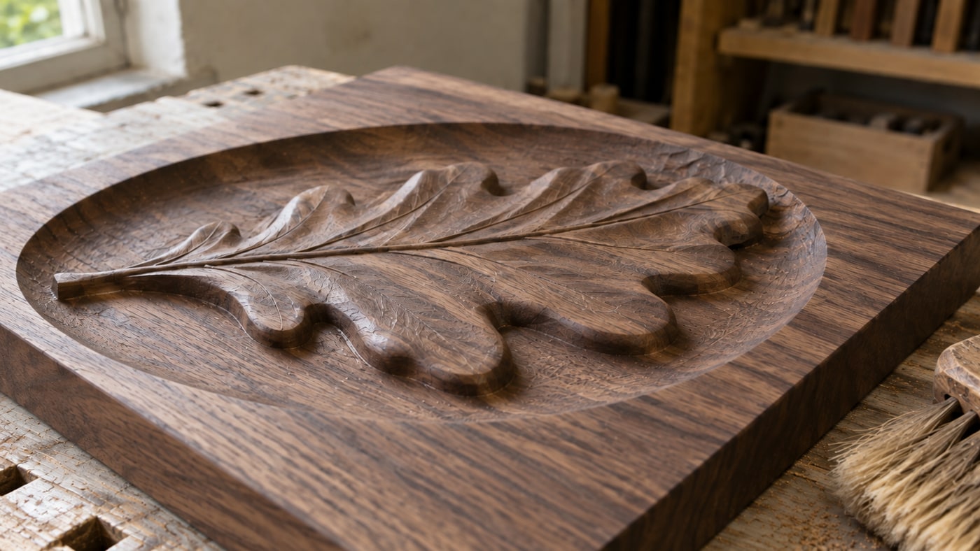
A leaf standing above the recessed field of a walnut panel has physical form: rounded lobes, a raised vein, and shadows that change with the light. An SVG outline describes the leaf's boundary. A relief model also needs heights across its surface.
The gap between those two things is a depth map, and the concept is much simpler than the results suggest. Once you know what the file actually holds, most of the confusion around 3D carving turns out to be confusion about one greyscale image.
Tip
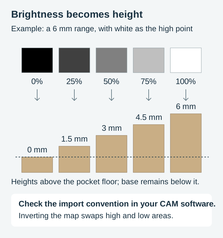
Short answer: a depth map is a greyscale image where brightness means height. In the white-high convention used below, white maps to the high point and black to the low point. Your height range and base thickness determine where those points sit in the stock. Your CAM software reads that image and carves a surface to match.
The whole idea, in one picture
Imagine a topographic map, but instead of contour lines it uses shades of grey. Each pixel says how tall the material should be at that exact spot.
- White is the highest point, usually the untouched surface of the stock.
- Black is the deepest point, cut down to your maximum depth.
- Greys are everything between, with lighter meaning shallower and darker meaning deeper.
That is all a depth map is. There is no hidden 3D geometry, no mesh, no model. It is an ordinary image file, usually PNG, that a piece of software has agreed to interpret as height rather than as a picture.
The software scales that height range to whatever depth you set. Tell it the darkest pixels sit six millimetres down and the map spreads its greys across six millimetres. Tell it twenty and the same file carves a much more dramatic relief from the same image, which is why one depth map can produce quite different-looking results.
Why depth maps are not SVG files, and never will be
Vector files describe outlines. An SVG holds a set of paths, and a path has no thickness in the third dimension because there is no third dimension in the format at all.
That does not make SVG the poor relation. It makes it a different tool. A vector path is exactly what you want for cutting a shape out, pocketing to a set depth, or V-carving, because those operations care about where the edges are and nothing else. Our CNC router SVG guide covers that side.
| SVG file | Depth map | |
|---|---|---|
| What it stores | Outlines and fills | A height value per pixel |
| Dimensions | Flat shapes at one depth | A continuous surface |
| Typical format | .svg | .png, .tiff, .bmp |
| Detail limited by | Path accuracy and bit width | Image resolution and bit depth |
| Typical operations | Profile, pocket, V-carve | 3D roughing and finishing passes |
| Runtime | Minutes | Hours |
| Suits | Signs, inlays, cutouts, engraved art | Plaques, wall art, sculpted panels |
That last row is not a small footnote. A vector job on a small sign might take fifteen minutes. The same subject as a full 3D relief with a roughing pass and a fine finishing pass can occupy a machine for most of a day, because the finishing pass has to walk the entire surface in narrow lines.
The two numbers that decide how good your carve can be
This is where most depth map disappointment comes from, and both causes are arithmetic rather than skill.
Bit depth, meaning how many height levels exist
An 8-bit greyscale image has 256 possible values. If you spread 256 levels across a one inch carving depth, each step is about a tenth of a millimetre. On a gentle slope, like a cheek or a curved sky, those steps can show up as faint terracing, a bit like contour lines on a hillside.
A 16-bit greyscale image has 65,536 levels. Across the same one inch that is a step far finer than any bit can physically render, so height quantization becomes much finer; source banding, conversion, and CAM sampling can still limit the result. If your software offers 16-bit and your source can supply it, take it, particularly for large smooth surfaces where the eye picks up terracing most easily.
There is a related trap in file format. JPEG is lossy, and the artefacts it introduces are invisible in a photograph but become real surface texture in a carving, since the software has no way to know that a slight brightness wobble was compression rather than intent. Save and exchange depth maps as PNG or TIFF, never JPEG.
Pixel resolution, meaning how fine the detail can be
Divide the image width in pixels by the carving width in inches to get pixels per inch. At 100 pixels per inch each pixel covers about a quarter of a millimetre of material.
Now compare that against the tool. A 1/8 inch ball nose is 3.17 mm across, and a fine finishing pass steps over by a fraction of that, commonly a tenth or so, which lands in the same quarter-millimetre neighbourhood. In other words, at roughly 100 pixels per inch the image and the cutter are matched.
That comparison gives a sense of scale, not a 100 PPI limit. A ball nose's contact geometry varies with depth and slope, and stepover is only one sampling direction. Image resolution, CAM model resolution, cutter shape, and toolpath tolerance all affect detail. Compare the final-size simulation before discarding higher-resolution source data.
Where depth maps come from
Hand-painted maps. Painting greys in an image editor, lighter for higher, darker for lower, using soft brushes for rounded forms. Total control, and slow.
Renders from 3D models. If a model exists, rendering its Z-buffer gives a mathematically exact depth map. This is how most commercial relief libraries are produced.
Conversion tools. Software that estimates a plausible surface from a flat image. Craftgineer's ReliefMaker does this in the browser and will output a carving-ready greyscale map from an illustration or photo, which is far quicker than painting depth by hand.
Straight from a photograph, which does not work. This deserves its own warning, because it is the single most common first attempt. A photograph records light, not height. Open a photo of a black dog against a pale wall, feed the brightness in as height, and the dog carves as a hole while the wall stands proud. The two are unrelated quantities that happen to share a range of greys.
Photographs can be the starting point for a depth map, but only through a tool that infers shape, or through manual work that separates the subject and rebuilds its form. If you want a photo turned into something carveable without going down the 3D road at all, our guide to converting photos to SVG covers the vector route.
What a good depth map looks like before it ever reaches the machine
Reading depth maps critically is a skill worth ten failed carves. Four things to check.
A clean background. The area around your subject should be a single flat value, usually pure black or pure white depending on whether you want it cut away or left at the surface. Any gradient in the background becomes a slope you did not ask for.
Hard edges where the subject stands proud. If the outline of a raised element fades gradually into the background, it will carve as a ramp rather than a step. Sometimes that is what you want. Often it means the map was blurred somewhere along the way.
Smooth, deliberate gradients inside forms. The greys within a shape are the shape. A muzzle rounds because the greys round. Blotchy or noisy greys become a lumpy surface, and no amount of sanding will unlump it.
Contrast that uses the full range. A map living entirely between 40 and 60 percent grey has thrown away most of its available depth resolution. Stretch it so the deepest point is at or near black and the highest at or near white, then set the actual depth in your CAM software where you can change your mind.
Software that reads depth maps
Vectric Aspire and VCarve. Aspire documents a direct Create Component from Bitmap workflow. VCarve can machine supported imported 3D models; do not assume importing an ordinary bitmap creates the same height component. Check the tools available in your installed product and version.
Carveco Maker and Maker Plus. The successor to ArtCAM, built around relief work, with strong tools for smoothing, blending, and merging height data before toolpathing.
Autodesk Fusion. Its Extrude Texture tool can use image values to alter mesh geometry. This is different from applying a visual material texture; prepare suitable geometry and a compatible manufacturing workflow.
Carbide Create Pro. Supports loading images as heightmaps, with 3D roughing and finishing toolpaths.
Whichever you use, check its own documentation for the import settings it expects, particularly on bit depth and on whether white or black is treated as the high point. That convention is not universal, and importing an inverted map produces a carving that looks like a mould of the thing you wanted.
Carving a depth map, step by step
- Set up the job to your real stock. Enter the actual thickness and set your Z zero deliberately, top or bottom, and remember which. Depth maps are unforgiving about Z because the whole surface is referenced to it.
- Import the map and scale it. Fit it to the area you want carved, keeping the aspect ratio so the subject does not stretch.
- Set the depth range. Decide how deep the darkest pixels go. Start conservatively: a shallower relief that reads well beats an ambitious one that runs out of material.
- Rough with a larger bit. A larger end mill or ball nose clears the bulk quickly, leaving a small allowance of material for the finishing pass to remove.
- Finish with a ball nose at a fine stepover. A smaller ball nose walking the surface in close passes is what produces the smooth modelled look. This is the pass that takes the hours.
- Simulate before you cut. Every one of these packages previews the result. Look at it properly, especially the background and the deepest areas, before committing several hours of machine time.
- Do not move the workpiece between passes. Roughing and finishing share an origin. If the stock shifts, the finishing pass carves in the wrong place and there is no recovering it.
For feeds, speeds, and stepovers, use the chart published by the maker of the bit you are running, matched to your material. Those numbers depend on your spindle, your machine's rigidity, and the specific cutter, which is why the people who make the cutters publish them and why a number copied from a blog post is worth very little.
The bit sizes below are the conventional pairings you will see in CAM tutorials and cutter catalogues, offered as a starting point rather than a measurement of ours. Match them against your own machine's capability and the cutter maker's documentation.
| Carving size | Common roughing bit | Common finishing bit | What changes |
|---|---|---|---|
| Small, around 6 by 6 inches | 1/4 inch end mill or ball nose | 1/8 inch ball nose | Fine detail survives; runtime stays manageable |
| Medium, around 12 by 12 inches | 1/4 inch ball nose | 1/8 inch ball nose | Finishing time climbs sharply with area |
| Large, 24 inches and up | 1/2 inch ball nose | 1/4 inch ball nose | A bigger finishing bit trades fine detail for a realistic runtime |
Material choice does as much work as tooling here. Tight-grained hardwoods like maple, cherry, and walnut hold fine modelled detail. Open-grained and soft woods fuzz, and the fuzz lands exactly on the delicate surfaces you spent hours cutting. Keep bits sharp, since a dull ball nose tears rather than shears and destroys detail on the pass that mattered most.
The relief look without the depth map
Here is the part that usually goes unsaid, and it is worth saying because it saves a lot of people a lot of machine hours.
A great deal of what reads as "carved relief" to the eye is shading, not geometry. Deep contour hatching that wraps a form, hatched shadow cast off a subject onto its background, a raised rim with a double line: those cues make a flat surface read as sculpted, and they work on any machine that can mark a surface.
That is what our relief medallion packs are. They are vector line art, drawn so that dense directional hatching models each form and a cast shadow lifts the subject off a striated background, giving the sculpted, carved-coin appearance without a single grey value in the file. They are not depth maps, and we would rather be plain about that than let the word "relief" do something misleading.
 North American Wilderness Relief Medallions30 designs, commercial license included$3.99
The practical difference is stark. A hatched relief medallion engraves on a laser in minutes, works on wood, slate, leather, and acrylic, and needs no roughing pass, no ball nose, and no 3D CAM licence. A true depth map carve gives you real physical depth that catches raking light and rewards being touched, at the cost of hours per piece and a machine capable of 3D toolpaths.
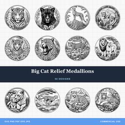 Big Cat Relief Medallions50 designs, commercial license included$3.99
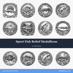 Sport Fish Relief Medallions30 designs, commercial license included$3.99
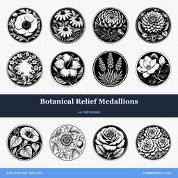 Botanical Relief Medallions46 designs, commercial license included$3.99
| Engraved relief look | True 3D relief carve | |
|---|---|---|
| Source file | Vector line art | Greyscale depth map |
| Machine | Laser, or CNC via V-carve | CNC with 3D toolpaths |
| Time per piece | Minutes | Hours |
| Depth you can feel | None, the surface stays flat | Real, several millimetres or more |
| Materials | Wood, slate, leather, acrylic, anodized metal | Tight-grained hardwood, modelling board |
| Best for | Coasters, ornaments, slate tiles, batch runs | One-off plaques, wall art, gallery pieces |
Neither is the upgrade of the other. If you sell at markets in volume, engraved relief is what your production schedule can actually support. If you are making a single showpiece, the depth map is what turns it into an object people ask to hold.
Where to go next
If you want the carved look on a CNC without the full 3D route, V-carving sits neatly in between, using bit geometry to produce varying width and apparent depth from flat vectors. Our V-carving tutorial walks through it.
If you want the fastest path to a finished relief-style piece, browse the relief medallion designs across the wildlife and nature and outdoors categories, or the full catalog. Every pack is $3.99, ships as SVG, PNG, JPG, PDF, and EPS, and includes a commercial license covering unlimited physical products, including print-on-demand fulfilment.
And if you are heading down the true 3D route, start small. A six inch panel in maple will teach you more about bit depth, stepover, and the difference between a good map and a bad one than any amount of reading, and it will do it in an afternoon rather than a weekend.
Designs for this project
North American Wilderness Relief Medallions30 designs, commercial license included$3.99Big Cat Relief Medallions50 designs, commercial license included$3.99Sport Fish Relief Medallions30 designs, commercial license included$3.99Botanical Relief Medallions46 designs, commercial license included$3.99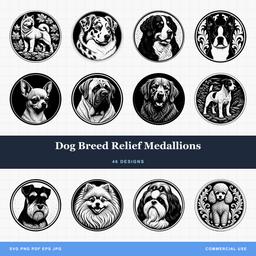 Dog Breed Relief Medallions46 designs, commercial license included$3.99
Frequently Asked Questions
What is a depth map?
A greyscale image where the brightness of each pixel stands for a height. With the common white-high convention, white is highest and black is deepest, with intermediate greys between them. Check the convention and inversion setting in your software. CAM software reads that brightness across the image and cuts a matching surface, which is how a flat picture becomes a carved relief.
Can I use a photograph as a depth map?
Not directly. A photograph records light, not height, so a black dog on a pale wall would carve as a deep hole where the animal should stand proud. Photographs have to be converted by a tool that estimates shape rather than simply reading brightness, or repainted by hand.
What resolution should a depth map be?
Choose resolution for the finished size, smallest useful features, cutter, stepover, and CAM model resolution. At 100 pixels per inch each pixel spans 0.254 mm, but this is an example, not a universal ceiling. Inspect the simulated surface at its final size.
Do SVG files contain 3D depth information?
No. An SVG describes flat outlines with no height data at all. You can pocket an SVG to one depth or V-carve along its paths, but any variation in height has to come from somewhere else, either a depth map or a 3D model.