You bought a design, opened it in your laser software, hit start, and the result looks nothing like the listing photo. Too light, too scorched, or somehow just an outline of the thing you wanted filled in. So you go searching for "laser engraving settings" and find a dozen tables that all disagree with each other.
Here is the uncomfortable truth behind those tables: numbers without a machine attached to them are close to meaningless. A 10W diode, a 20W diode, and a 60W CO2 tube hitting the same walnut board need wildly different speed and power, and even two units of the same model drift apart as lenses age. What actually gets you repeatable results is knowing where trustworthy starting numbers come from, how to test them on your own machine in ten minutes, and how to prepare the SVG so the laser interprets it the way the designer intended. This guide covers all three.
Tip
Short answer: get starting settings from your laser manufacturer's own material library, then refine them with a test grid on scrap before every new material. The file matters as much as the numbers: use closed boundaries for filled vector areas, assign the operation deliberately, and inspect the preview. On slate, marked areas become pale; that does not automatically require inverting a simple silhouette.
The software you'll be using
Your SVG has to pass through control software before the laser ever fires, and that software determines how the file's paths get interpreted.
LightBurn is the standard choice for most diode and CO2 machines, including Ortur, xTool, Atomstack, OMTech, and many others. It imports SVG natively, keeps the file's structure intact, and gives every color its own layer with independent settings. We wrote a full walkthrough in our LightBurn SVG tutorial, and it is the software this guide assumes when it mentions specific features.
LaserGRBL is free and open source, aimed at GRBL-based diode lasers. It handles SVGs but with a simpler toolset. A fine way to start without spending money, and plenty of people never outgrow it.
Manufacturer apps like xTool Creative Space and the Glowforge web app trade flexibility for convenience. They accept SVG uploads directly and, importantly for this guide, ship with built-in settings libraries matched to the exact machine you own. Glowforge owners should read our Glowforge SVG guide for the specifics of that workflow.
Cut, score, engrave: how the software reads your SVG
An SVG is a set of vector paths, and laser software gives you two fundamentally different ways to run them.
Line mode (sometimes called vector or cut mode) traces along the path itself. At high power and low speed it cuts through the material. At low power and higher speed the same mode produces a score, a single crisp burned line, which is how fine linework in a design gets rendered.
Fill mode (raster or engrave mode) ignores the path as a line and instead sweeps the laser back and forth across the interior of the shape, burning every filled region. This is what produces the shaded, picture-like engraving on a finished board.
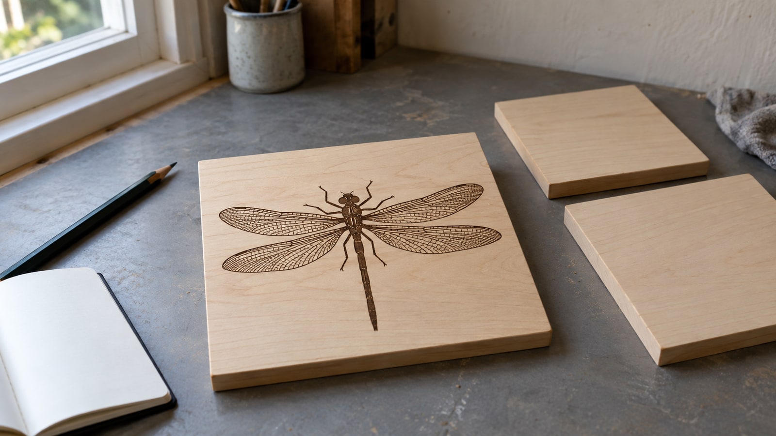
This distinction is where most first attempts go wrong, and it is a file question, not a settings question. Fill mode needs closed boundaries. In LightBurn, a closed source path without a fill can still be assigned Fill; other software may use the source fill and stroke to choose an initial operation. An open path has no interior to fill, so the software either skips it or renders a stray line. Our design files are built for this: every shape is a closed, filled path, and the hatching and cross-hatch shading you see in the detailed engraving styles is drawn as actual vector geometry rather than a gray raster image. That means the shading engraves at full crispness at any size, instead of going muddy the way a scaled-up bitmap does.
 Detailed Wolf Designs40 designs, commercial license included$3.99
The four settings that actually matter
Every material table you will ever read is just combinations of these four values. Understand what each one does and the tables stop being magic numbers.
| Setting | What it controls | Raise it and... | Lower it and... |
|---|---|---|---|
| Speed | How fast the head travels | Lighter, shallower marks, faster jobs | Darker, deeper marks, more heat in the material |
| Power | Beam intensity, as % of max | Deeper burn, risk of scorch or cut-through | Lighter mark, risk of no mark at all |
| Line interval (mm) | Spacing between fill scan lines | Fewer scan lines | More scan lines and more overlap |
| Passes | How many times the job repeats | More depth built up gradually | Single pass, all heat delivered at once |
A few notes that the one-line table can't carry:
Speed and power trade against each other. Half the speed at half the power lands in roughly the same place as full speed at full power, but the slower version soaks more heat into the surrounding material. On wood that means wider scorch halos. When two combinations give the same darkness, prefer the faster one.
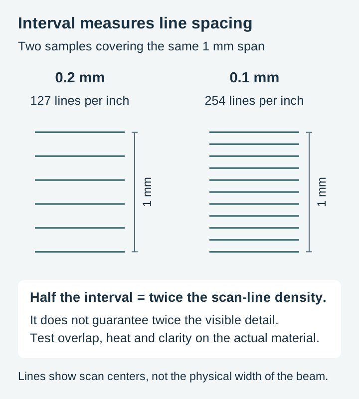
Line interval and line density are inversely related. Divide 25.4 by interval in millimeters to get lines per inch. Halving the interval doubles the scan-line density, while total time also depends on travel and acceleration. Whether adjacent marks touch depends on the beam and material. Use an interval test to judge overlap and detail.
Multiple gentle passes beat one aggressive pass on materials that dislike thermal shock. Slate is the classic case: it can pit or flake under a single hot pass but takes two lighter passes gracefully.
Focus is the invisible fifth setting. An out-of-focus beam spreads its energy over a wider dot, so every number in your table effectively changes. If results suddenly stop matching your saved settings, check focus before you change anything else.
Where the actual numbers come from
We are a design shop, not a laser test lab, so you will not find a speed and power table here with numbers we cannot stand behind. What we can tell you is where the reliable ones live.
Your machine manufacturer's material library is the first stop. xTool publishes official settings for each of its machines and maintains them inside Creative Space, Glowforge ships tested Proofgrade settings for every material it sells, and most diode laser brands include a starting-point chart in the manual or on their support site. These numbers are worth more than any third-party table because they were produced on your exact model, wattage, and lens.
LightBurn's material library feature lets you save a named entry per material and machine once you have dialed something in, and makers share exported libraries for popular machines. Treat any shared library as a starting point rather than gospel, since the other person's focus, lens condition, and air assist all differ from yours.
Whatever the source, the framing is always the same: these are starting points to test from, never numbers to run blind on your final workpiece.
The ten-minute test grid
This is the habit that separates consistent results from lucky ones. Before engraving any new material, burn a small test on scrap of the same stock.
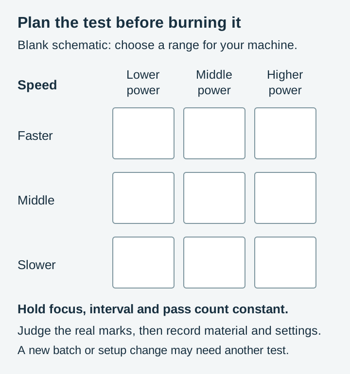
- Generate a grid. LightBurn has a built-in generator under the Laser Tools menu called Material Test. It burns an array of squares, stepping power along one axis and speed along the other. If your software lacks the feature, a hand-made row of five small squares at increasing power does the same job.
- Bracket around the manufacturer's number. If the library says a given power, test a spread from well below to slightly above it at your intended speed.
- Read the result in good light. You are looking for the square that is evenly dark without a scorched halo, and on wood, without visible charring when you rub a finger across it.
- Save the winner. Write it in the material library with the material, thickness, and date. Six months from now this note is gold.
Keep the tested settings as a baseline. A new batch, changed focus or optics, different masking, or another setup change can justify testing again.
Preparing the SVG before you press start
Settings get all the attention, but a few minutes with the file prevents most of the failures people blame on settings.
Check fills versus strokes
Check how your software interprets source fills and strokes, then inspect the assigned operation. In LightBurn, choose Fill for closed areas you want covered; a source fill is not required. A closed shape can still be processed as a line when its layer is Line. Preview confirms planned coverage.
Hunt for strays
Zoom out and select everything. Stray points, invisible leftover elements, or duplicate paths from an editing session can add phantom marks or double-burned lines. In LightBurn, Edit > Select All shows you everything on the workspace including things you didn't know were there, and Edit > Delete Duplicates clears doubled paths.
Check contrast on dark materials
On slate and other dark surfaces, the laser marks lighter than the background, the exact opposite of wood. A simple filled silhouette usually becomes a pale silhouette without changing its geometry. Photographic tones and shading may need separate preparation or inversion; judge them in a preview configured for the material. Our slate-specific packs are drawn for this reversed contrast from the start, which is exactly why they exist as a separate line, and our slate engraving guide walks through the whole material.
Confirm the size
Vector files scale freely, so nothing stops a design arriving on your workspace at the wrong physical size. Check the dimensions readout against your workpiece before framing the job, not after the laser starts moving.
How materials behave under the beam
Numbers vary machine to machine, but material behavior is consistent, and knowing it tells you what to expect from your test grid.
Light woods like basswood and birch ply give the strongest contrast and are the most forgiving canvases for detailed work. Hardwoods such as maple and walnut need more energy for the same darkness and their pronounced grain shows through the engraving, which reads as character on rustic pieces and as noise on fine portraits.
Slate marks light gray against near-black and rewards gentle treatment, since aggressive single passes can flake the surface. Leather (vegetable tanned) marks at very low power and crosses from a clean brand into an acrid burn quickly, so start your test bracket lower than instinct suggests.
Cast acrylic engraves to a frosted white that looks superb backlit; extruded acrylic engraves clear-ish and disappointing, so check which one you bought. Anodized aluminum can change color under a suitable laser without the anodized layer necessarily being stripped to bare metal. Ceramic tile takes a permanent mark with a coating method such as the maker-community "Norton white tile" technique, where a sprayed titanium-dioxide layer fuses to the glaze.
For a deeper pass over choosing stock, see our guide to the best materials for laser engraving.
Habits that keep results clean
- Mask wood before engraving. Paper transfer tape or painter's tape over the surface catches the smoke residue that otherwise stains the area around the burn. Peel it after the job for a clean border.
- Ventilate properly. Exhaust is a safety requirement first, but it also pulls smoke off the workpiece before it can settle back and yellow the surface.
- Clean the lens on a schedule. Smoke haze on the optics quietly eats your power, and you will chase "wrong settings" for an hour before thinking to look up.
- Fix the workpiece down. Tape, clamps, or a honeycomb bed with pins. One nudge from the air assist mid-job ruins forty minutes of engraving.
- Keep notes. Record material batch, focus, masking, air assist, and tested settings so you know when a previous result is relevant.
Grayscale and depth: the advanced end
Some designs use shades of gray rather than pure black, and laser software can map those grays to varying power. Lighter grays engrave shallow, darker grays deep, which produces photographic tonality on wood and genuine relief on materials that ablate cleanly.
This is the same idea that drives 3D relief carving from depth maps, where the gray value literally encodes depth. If that direction interests you, our guide to depth maps for CNC carving explains how those files work and where a laser fits into the picture.
Put a real design under the beam
Test grids are how you learn your machine, but the reason you own the machine is the finished piece. Every pack below is drawn for engraving work: solid closed paths, vector shading that stays sharp at any scale, and files delivered as SVG, PNG, JPG, PDF, and EPS so they drop into whichever software you run. Each pack is $3.99 and includes a commercial license, so what comes off your laser bed can go straight to the craft fair table.
 Deer Designs For Slate30 designs, commercial license included$3.99
 Butterfly Engraving Designs30 designs, commercial license included$3.99
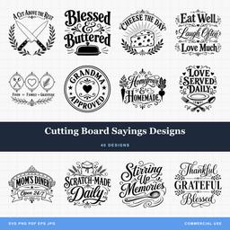 Cutting Board Sayings Designs40 designs, commercial license included$3.99
Pick a design, burn one grid on scrap, and the settings question answers itself.
Designs for this project
Frequently Asked Questions
What speed and power should I use for laser engraving wood?
There is no universal number, because wattage, lens, and focus differ between machines. Start from your laser manufacturer's own material library, then burn a small test grid on scrap of the same wood and pick the square that is evenly dark without scorching.
What DPI is best for laser engraving?
A 0.1 mm line interval gives 254 lines per inch, but the useful interval depends on beam size, focus, and material. Test spacing on your setup. Halving the interval doubles scan-line density; it does not guarantee more visible detail.
Why does my design engrave as an outline instead of filled in?
Check whether the shapes have closed boundaries and whether the software has assigned Fill or Line. LightBurn can fill a closed path even if the original SVG had no fill. Workspace wireframe is separate from the operation; inspect Preview.